Parallel To Serial Converter Chip
Need Help.
Customer Service
Track My Order
Frequently Asked Questions
International Shipping Info
Send Email
Mon-Fri, 9am to 12pm and
1pm to 5pm U.S. Mountain Time:
303 284-0979
Chat With Us
USD
US Dollar
Canadian Dollar
Australian Dollar
British Pound
Euro
Manage Currencies
sparkfun.com
Shop
Learn
AVC
Forum
Data
Shopping Cart
0
items
log in
register
Shop
Learn
Products
Start a Project
Blog
Tutorials
Videos
Wish Lists
Distributors
Support
Desktop Site
Back to main menu
New Products
Top Sellers
SparkFun Originals
Clearance 2016
Stepoko
Sale
Gift Certificates
ArduinoBoardsOtherShieldsAudioBooksBreakout Boards CablesAudioEthernetHook UpParallelSerialUSBVideo–ComponentsAVR MicrocontrollersButtons/SwitchesELGeneralGeneral ICs LEDs10mm3mm5mm7-SegmentOtherSMDOscillatorsPICAXE MicrocontrollersPIC MicrocontrollersSMD ICs Development ToolsAndroid ArduinoBoardsOtherShieldsARMAVRBeagleChumbyFPGAGadgeteeriPodJavaLPCmbedMSP.NETpcDuinoPICPICAXEPropellerPSoCRaspberry PiRoombaTeensyWiringWIZnetDings and DentsEducators GPSAccessoriesAntennasEval BoardsModulesIntel Edison IoTESP8266Intel EdisonParticle PhotonRFduinoKits LCDsColorMonochrome PrototypingBatteriesBoardsConnectorsEnclosuresGeneral ProgrammersARMAVRPICPICAXESocketsSolarWireRaspberry Pi RoboticsDriversGears HardwareCouplers/CollarsFastenersShaftsSpacers/StandoffsStructuralTubingKits MotorsAccessoriesDC/GearmotorOtherServoStepper Mounts/HubsBearing BlocksCamera MountsHubs/ClampsMotor MountsServo MountOtherPulleys and BeltsSprockets and ChainWheels Sensors Accelerometers1-axis3-axisBiometricsCapacitiveCurrentFlex / Force Gyros2-axis3-axisIDIMUInfraredLight / ImagingMagnetoProximityRadiationSoundTemperatureVernierWeatherSwag Tools3D PrintingCNCHand ToolsHot-Air ReworkInstrumentsOrganizationPower SuppliesSoldering WearablesElastoLiteLilyPadMaterialsPowerWidgets WirelessAntennasBluetooth CellularAntennasEval BoardsModulesGeneralNordicWiFi ZigBee 802.15.4900MHzSeries 1 802.15.4 Series 2 ZigBee RetiredAudioBooksBreakout BoardsCablesComponentsDevelopment ToolsDings and DentsEducatorsGPSIoTKitsLCDsPrototypingRetailRoboticsSensorsSwagToolsWearablesWidgetsWireless
Home
Product Categories
Components
8-Bit Parallel-In/Serial-Out Shift Register - 74HC165N
Retired Product
This product has been retired from our catalog and is no longer for sale. This page is made available for those looking for datasheets and the simply curious.
COM-09519
RoHS
Creative Commons
images are CC BY-NC-SA 3.0
Share
Use this URL to share:
Share on Google
Share on Tumblr
Submit to reddi
Share on Twitter
Share on Facebook
Pin It
Favorited
Favorite
1
Wish List
Skills
2
Soldering
Programming
3
Electrical Prototyping
Description: Replacement: None. We are no longer carrying this shift register in our catalog. This page is for reference only.
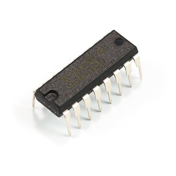
The SN74HC165N is a neat little IC that will take an input of up to 8 parallel lines and produce a single, serial output. You can even daisychain 2 together to add even more parallel lines. It s a great way to increase the number of inputs on a microcontroller.
This chip works with a voltage supply anywhere in the range of 2-6VDC, and at clock frequencies of up to 29MHz 6VDC.
Comes in a 16-pin DIP package.
Features:
Wide Operating Voltage Range of 2 V to 6 V
Parallel-to-Serial Data Conversion
Outputs Can Drive Up To 10 LSTTL Loads
Low Power Consumption, 80-μA Max ICC
4mA Output Drive at 5 V
Low Input Current of 1 μA Max
Complementary Outputs
Direct Overriding Load Data Inputs
Gated Clock Inputs
Documents:
Datasheet
Arduino Example
Recommended Products
Page 1 of 4
Added to your cart.
SparkFun Recommended
Arduino Pro Mini 328 - 5V/16MHz
In stock
DEV-11113
It s blue. It s thin. It s the Arduino Pro Mini. SparkFun s minimal design approach to Arduino. This is a 5V Arduino running
9.95
72
44
Arduino Pro Mini 328 - 3.3V/8MHz
DEV-11114
It s blue. It s thin. It s the Arduino Pro Mini. SparkFun s minimal design approach to Arduino. This is a 3.3V Arduino runnin
22
20
Arduino Pro 328 - 5V/16MHz
DEV-10915
It s blue. It s skinny. It s the Arduino Pro. SparkFun s minimal design approach to Arduino. This is a 5V Arduino running the
14.95
5
Breadboard - Classic
PRT-00112
Your first exposure to electrical engineering - the bread board. Who knew it would bring so much frustration.
This is your
6
7
Page 2 of 4
Arduino Pro 328 - 3.3V/8MHz
DEV-10914
It s blue. It s skinny. It s the Arduino Pro. SparkFun s minimal design approach to Arduino. This is a 3.3V Arduino running t
Shift Register 8-Bit - SN74HC595
COM-13699
The SN74HC595N is a simple 8-bit shift register IC. Simply put, this shift register is a device that allows additional inputs
0.95
7-Segment Display - 4-Digit Red
COM-09483
This is a basic, 4-digit 7-segment display - red in color. It has a common anode. The display features one decimal point per
1.95
SparkFun Shift-In Breakout - SN74HC165
23 available
BOB-11733
The SN74HC165N is a neat little IC that will take an input of up to 8 parallel lines and produce a single, serial output. It
3.95
Page 3 of 4
Shift Register 8-Bit High-Power - TPIC6B595
COM-00734
Simple shift register IC that can control high-voltage/high-current devices directly. Clock in data and latch it to control d
2.25
4
7-Segment Display - 4-Digit Kelly Green
COM-09482
This is a basic, 4-digit 7-segment display - green in color. It has a common anode. The display features one decimal point pe
7-Segment Display - 4-Digit Blue
COM-09481
This is a basic, 4-digit 7-segment display - blue in color. It has a common anode. The display features one decimal point per
2.5
DIP Sockets Solder Tail - 16-Pin 0.3
PRT-07938
Dip sockets for all your prototyping needs. If you ve ever had to de-solder a dip part from a circuit board, you know how val
0.5
Page 4 of 4
7-Segment Display - 4-Digit White
COM-10931
This is a basic, 4-digit 7-segment display - white in color. It has a common anode. The display features one decimal point pe
1.9500
1.25
7-Segment Display - 4-Digit Yellow
COM-09480
This is a basic, 4-digit 7-segment display - yellow in color. It has a common anode. The display features one decimal point p
Previous
Next
Comments
Reviews
Customer Comments
Log in or
register to post comments.
Log in to post comments.
bluewraith
/
about 5 years ago
/
Isn t this the same type of chip that the original NES used in its controllers.
JordanDee
about 3 years ago
Yes, same type and this serves the same purpose. It s a shift register for inputs, which in the NES controller s case, for buttons.
The one in the NES specifically is the HD14021B for reference.
BrainSlugs83
One of these three are wrong: The description, the datasheet, or me.
Datasheet says that the fastest input transition rise/fall time is 400 ns.
Description says you can run it up to 29 MHz.
My math says 1 / 400 10-9 2,500,000 Hz or 2.5 MHz – that s more than an order of magnitude slower.
is assuming 6V, which appears to be the maximum voltage / max-speed.
SFUptownMaker
400ns is the CAP on the rise time- the maximum that it should be allowed to be. Faster rise/fall times are allowed, but not slower ones. If you read the note at the bottom of the chart, you ll see WHY slow rise times are bad- if the input lingers in the undefined region too long, it can cause the circuit to double-clock. It also increases the power dissipation of the device, which can sometimes be an issue.
Hey, thanks for the reply.
I guess this leaves me a little bit confused on a couple of counts:
Where does the 29 MHz number in the description come from.
It is the maximum rise fall time at 6 volts, which I understood to mean and please correct me here that the chip could sometimes take up to 400 nano seconds to transition to it s new output state based on the input I send it is that incorrect. – As in: it could go faster, but there isn t any indication from the chip when it does, so if I change it s state and try to read it s outputs faster than 400 nano-seconds at 6 volts, doesn t this mean that sometimes I will get the old or possibly undefined data.
The note at the bottom is specifically related to voltages, not timing – it says that if I power it in the range of. 5 volts to 1.5 volts that it could cause double clocking and incorrect data / undefined states.
Apologies for being a bit of a newb about this. Clearly, there s something here that I m missing.
I think there may be a tutorial in this- it s a good example of how values in a datasheet can be a little opaque to the neophyte.
Pages 6, 7, and 8 have waveform diagrams and definitions of the various parameters related to them. Basically, the 29MHz number comes from the fastest signal that can propagate through the device without violating setup and hold times and allowing outputs to transition past their threshold levels.
The time to transition to a new state is generally referred to as propagation delay. On page 7, you ll see tpd- that s what you re looking for. The rise/fall time is the time from usually 10 of VCC to 90 of VCC or vice versa.
That note at the bottom is both about time and voltage- it relates to the time a signal can remain in a voltage range without causing a problem.
I will definitely try and do a tutorial about this, soon.
Thanks for all the help. I did find this application note about floating inputs – and it explains the input transition rise/fall rate stuff, and why it s a bad idea to transition slowly at least I hope this is related..
I do see the 29 MHz spelled out explicitly in the datasheet now that I inspect it closer derp. – However the math still seems weird to me, using the tPd for 6V still gives me like 31 MHz instead of 29 It s Megahertz not Mebihertz, right. lol.
As for the tutorial, I did see the original SparkFun tutorial on reading datasheets, but it was extremely basic – a lot of the terms are still black magic to me.
As for the device losing data if I go too slow – is that only if I transition the voltage between Vss and Vcc and versa-vice too slowly or is that if I provide the clock pulses too slowly.
JRiggles
about 4 years ago
I can use this in place of a CD4021, right.
Yes, the CD4021 is very similar to this one.
nerdboy64
Supposedly this part is in Eagle, but I can t find it and a search turns up blank. Anybody know what library it s under.
MikeGrusin
It s in the standard not Sparkfun libraries, try 74xx-us / 74 165 / 74LS165N. The LS is a different family than HC, but the footprint is the same, and you can always rename the part in your schematic for accuracy.
Member 316815
What if i need to read 8 analog input.Will it work too or do i need and adc on every input before going into the register.
Thanks.
Mozler
What kind of analog input. Can you describe the surrounding circuit. I think it depends on the current you expect the device to sink/source. What is the meaning of the analog levels, i.e. is it the same as digital level where some range means high and another is low. In any case, you don t need and ADC, if you don t want to connect the analog signal directly to the input, connect the analog signal to a transistor or such and place the transistor output as input to the device.
So there are no way to run this circuit with only 3 cables. I.e. using only clk, ser, and Qh to read. So we also need to manipulate SH/LD.
EDIT: Never mind the question, I didn t think. You don t need ser. So you can run it of clk, Qh, and SH/LD.
mooselodge
Is this the correct shift register to use to control an array of 60 or so LED s.
many thanks
Peter
zampire
This is a parallel-in/serial-out shift register, meaning that you can read from the parallel inputs, but you can t write to them, as you would need to do to control LEDs. You need 74HC595s, which are serial-in/parallel-out shift registers.
CF
I think you want some 74HC595 s.
SeanA
Anyone know if/where this part exists in the SF Eagle library.
Mr. Cruz
It would appear not. However, Eagle already has the part in it s libraries.
Just search for 165when you re going to add a part.
WilliamK
And here s a complete code that can be used as a library, reading 16 stages using the same 2 chips as the arduino example above.
define BTploadPin 25 // Parallel load pin the 165
define BTdataPin 27 // Q7 pin the 165
define BTclockPin 26 // Clock pin the 165
class Buttons
public:
Buttons
pinMode BTploadPin, OUTPUT ;
pinMode BTclockPin, OUTPUT ;
pinMode BTdataPin, INPUT ;
digitalWrite BTclockPin, LOW ;
digitalWrite BTploadPin, HIGH ;
memset Clicked,false,sizeof Clicked ;
memset prevHigh,false,sizeof prevHigh ;
bool Tick
SomethingChanged false;
digitalWrite BTploadPin, LOW ;
for int i 0; i 16; i
tempButton digitalRead BTdataPin ;
if tempButton LOW prevHigh 15-i HIGH
Clicked 15-i true;
SomethingChanged true;
prevHigh 15-i tempButton;
digitalWrite BTclockPin, HIGH ;
return SomethingChanged;
void Reset void memset Clicked,false,sizeof Clicked ;
boolean Clicked 16 ;
private:
boolean SomethingChanged;
unsigned int tempButton;
unsigned int prevHigh 16 ;
;
Customer Reviews
No reviews yet.
Sharing
Ingenuity
GitHub
YouTube
Vimeo
Google Plus
Flickr
RSS
SparkFun is an online retail store that sells the bits and pieces to
make your electronics projects possible. Whether it s a robot that can
cook your breakfast or a GPS cat tracking device, our products and
resources are designed to make the world of electronics more accessible.
In addition to products, SparkFun also offers
classes and online tutorials to help educate
individuals in the wonderful world of embedded electronics.
About Us
About SparkFun
SparkFun Education
Feeds
Jobs
Contact
Help
Shipping
Return Policy
FAQ
Programs
Educator Discount
Partner with SparkFun
Tell Us About Your Project
Sell Your Widget on SparkFun
Become a SparkFun Distributor
Community
SparkFun IRC Channel
Take the SparkFun Quiz
SparkFun Kickstarter Projects
What s on your mind.
For which department.
Please include your email address if you d like us to respond to a specific question.
SparkFun Electronics
Niwot, Colorado
Site Map
Terms of Service
Privacy Policy
Your Account
Log In
Register
Password
Forgot your password.
No account. Register one.
This USB to Serial converter allows you to connect a RS-232 serial device such as a modem to a USB port on your Desktop or Laptop PC. Connect a RS-232 serial.
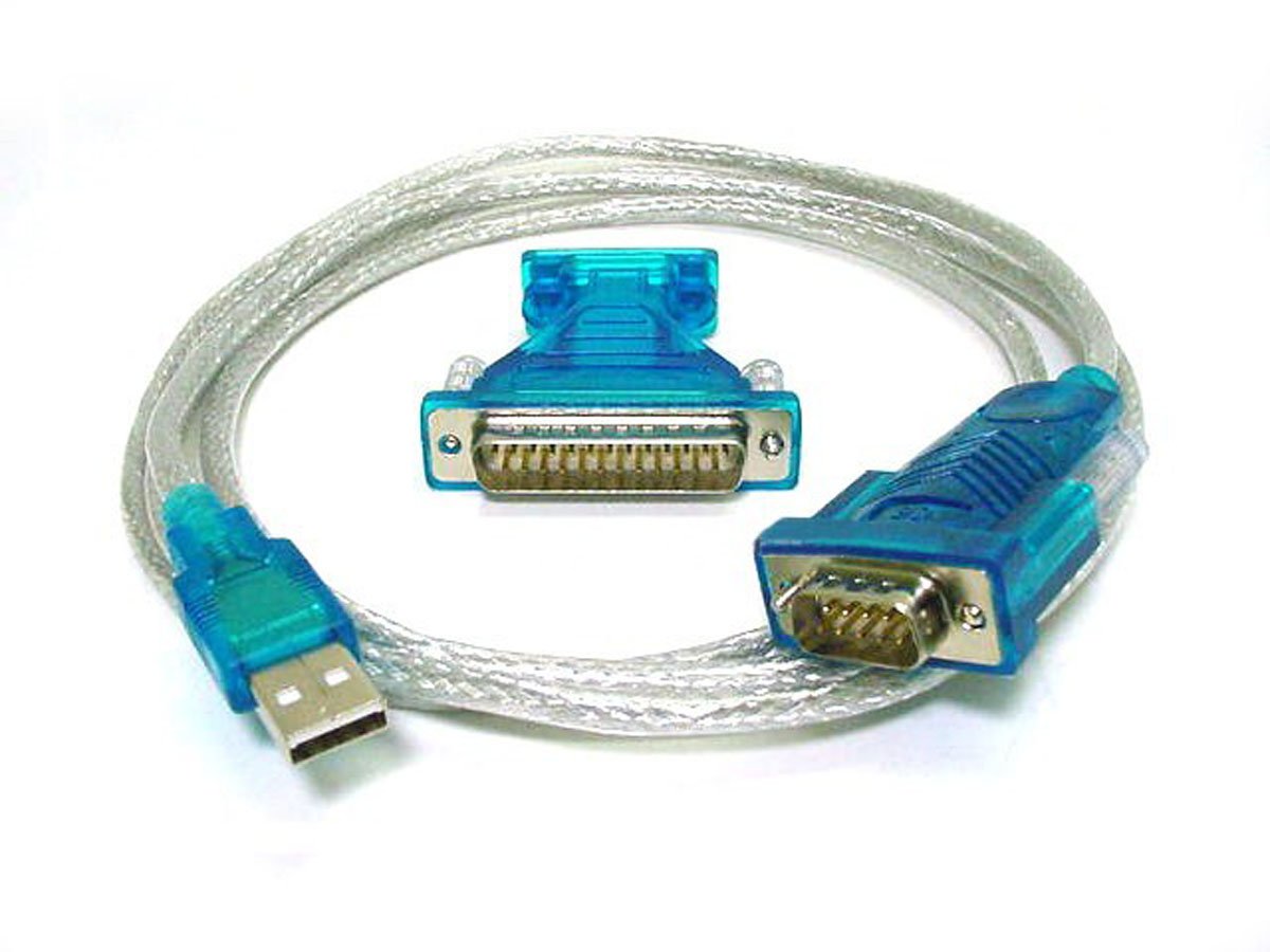
USB to Serial Converter -, Connects One Serial Device to a USB Port, Prolific PL-2303RA Chip, 45 cm 18 in.
The PEX1S1PMINI 1S1P Mini PCI Express Serial Parallel Card w/ 16950 UART turns a mini PCIe slot into 1 RS232 DB9 Serial port and 1 Parallel port. A native PCI.

USB to RS232 DB9 male Serial / DB25 male Converter Cable
Features:
Length: 70 inches
Connectors: One USB-A to DB9 Male and DB25
Supports automatic handshake mode
Over 1Mbps data transfer rate
Supports remote wake-up and power management
96-byte buffer each for upstream and downstream data flow
Easy installation
Works with cellular phones, PDA, digital cameras, modems, and ISDN terminal adapters
Frees your RS-232 ports for other uses
No IRQs, no IRQ conflicts
Requires Microsoft Windows 98, Me, NT, 2000, XP, Vista, Windows 7 32 and 64
Support Files:
Drivers for Windows XP/Vista/7 Nov 28, 2007.

Pros: - Superior construction - Variety of drivers available - Attractive connectors and cabling. Cons: None. This USB-to-RS232 cable is the core item in provisioning.
USB STK200 AVR Starter Kit with JTAG ICE The STK200 AVR board designed by Kanda for Atmel AVR devices is the most successful starter kit EVER produced.